Construction of Bradycardia Pacing Leads and Principles of Electrical Stimulation of the Heart
Basics of Pacing Leads
Pacing leads have come a remarkable journey…..now only to be threatened by lead-less pacemakers !
Concepts of delivering Electrical Impulses to the Heart
In conventional electrical diagrams current is said to flow from (+) pole of a battery to the (-) pole i.e. positive to negative. However, it is now known that an electrical current consists of a stream of electrons and electrons leave the battery at its negative pole.
To further confuse matters, we have a cathode and an anode which also says something about the electrical flow. Cathode denotes the pole where electrons are received and the anode is the pole where electrons are emitted. Hence a conventionally positive pole of a discharging battery would its cathode (i.e. electrons come in )!
The term cathode and anode are relative to the load (or source) i.e. when we say anode of a battery, it would be connected to the cathode of the load (the electrons exit at the anode of the battery and received at the cathode of the load). The most simplest way to remember anode and cathode is :
- Anode = electrons go Away
- Cathode = electrons Come here
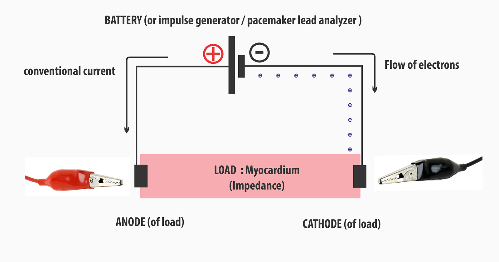
Figure : In conventional electrical diagrams, current flow is from positive (+) to negative (-). However in reality the current is a flow of electrons, which actually leave the negative pole of a battery which is also termed anode of the battery. However to understand certain concepts in cardiac pacing, it is better to name current flows the direction of electron flow using anode and cathode rather than assuming the conventional notation. The bulldogs clips represent application of them during lead testing. In this diagram, electrons are seen to exit the negative pole and enter the myocardium at the cathode of the electrode – this is termed cathodal capture which is an important concept in electrical stimulation of the heart (see below)
The modern pacemaker leads are bipolar leads : they consists of two electrical channels encased in an insulating material. One channel conducts the electrical impulse towards the lead tip and the other channel completes the circuit back to the pacemaker. In older systems, the lead consisted only of one channel which would deliver the impulse and the circuit is completed by the chest wall tissues which are in in contact with the pacemaker body (metal can) – this was referred to as unipolar pacing.
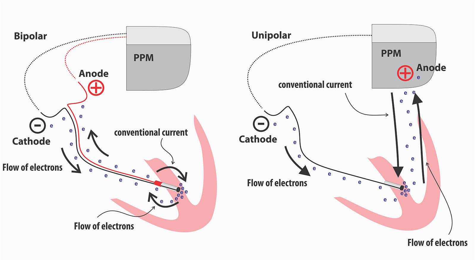
Figure : Bipolar and Unipolar pacing. PPM = Pacemaker. Note cathodal stimulation as shown by entry of electrons to the myocardium at the cathode. Cathodal stimulation achieves better electron density at the site of stimulation to initiate an action potential.
Myocardial capture requires a high local current density at the point of contact and to increase the current density, the lead tip electrode were made as small as possible which also increased its resistance – the high resistance helped preserve battery life as the current flow was reduced. Therefore by having a small tip, a high local current density was achieved at low current flows

Figure : Current density vs geometric size of lead
However, the small tip with a high concentration of electrons led to the polarization phenomenon and to counteract that, the tip surface was roughened using porous / woven material which increased the microscopic contact area of the lead tip without increasing its geometric size. Despite this some polarization occurs and leads to after-potentials soon after the initial impulse which if sensed in the pacemaker circuitry, can lead to inhibition of pacing. Post paced blanking events (Ventricular blanked and atrial blanked periods) prevent detection of these after-potentials.
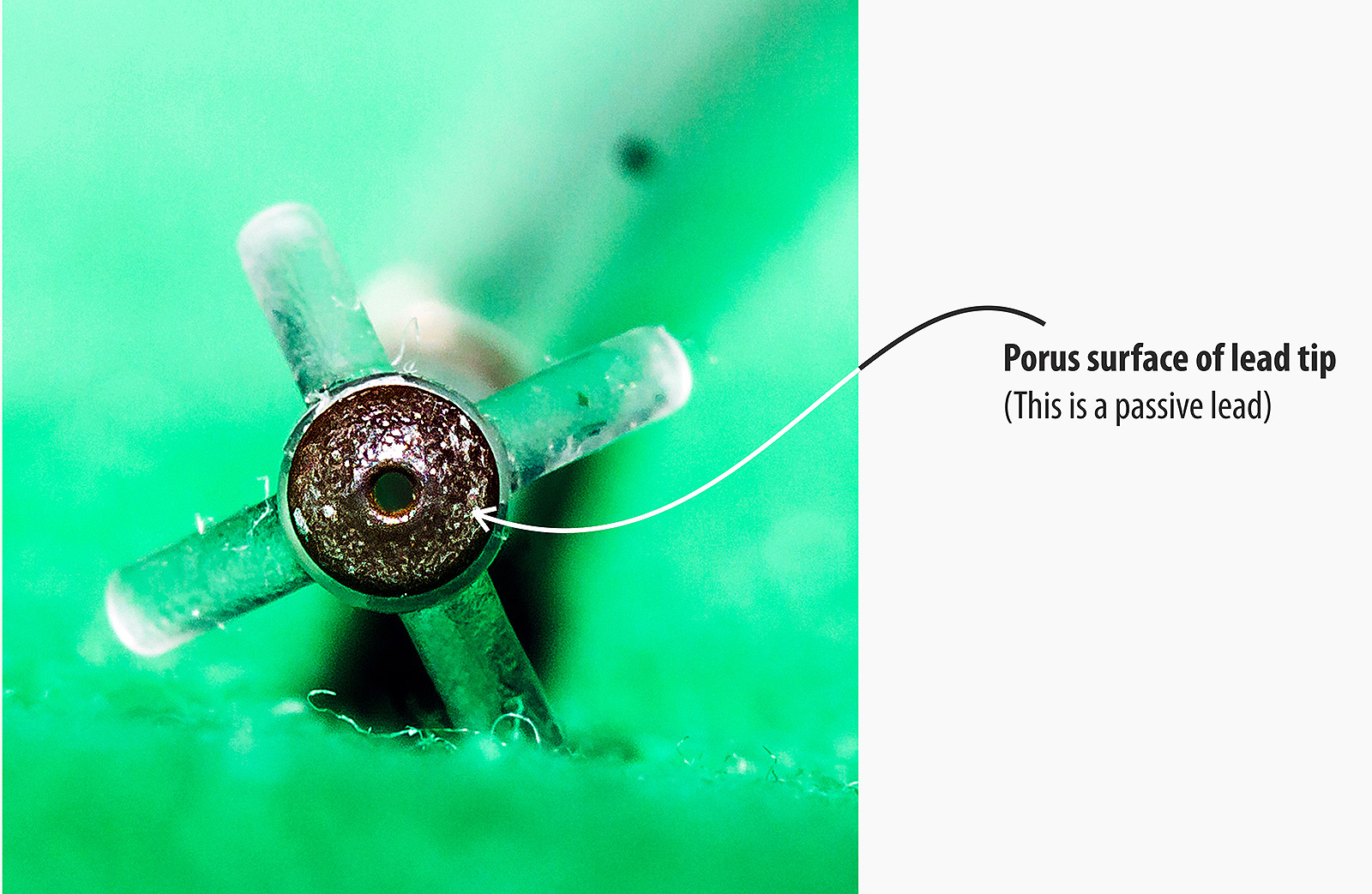
Figure : Roughened surface of lead tip. This increases the microscopic contact surface are without increasing the lead tip geometric size. The current density relevant for myocardial capture depends on the lead geometric size but the polarization phenomenon depends on the microscopic contact area.
In unipolar systems, the anode was the pacemaker canister (can) and it is in contact with the pectoralis major muscle at the pacemaker pocket floor. To prevent muscle capture, the current density must be low and therefore the anode had to have a large surface area which is automatically achieved as the pacemaker canister was the anode. In bipolar systems, the ring electrode acts as the anode and since there is no issue in muscle capture, the ring electrode has a small geometric surface. (but see anodal stimulation below). Despite large surface, sometimes the current density can increase above the capture threshold of the pectoralis major muscle and cause contractions in the pocket during unipolar pacing – especially when high outputs are used.
Anodal vs Cathodal Stimulation
Early on, it was noted that cathodal stimulation (i.e. where electrons “enter” the muscle from the electrode) had desirable properties in comparison to anodal stimulation (i.e. capturing the myocardium at the point where electrons from the muscle converge on the electrode). The capture thresholds were low and the electrode corrosion was minimal during cathodal stimulation.
It should be noted that during cathodal stimulation, capture occurs at the onset of the impulse (i.e. leading edge) whereas in anodal stimulation, capture occurs at end of the impulse (i.e. trailing edge).
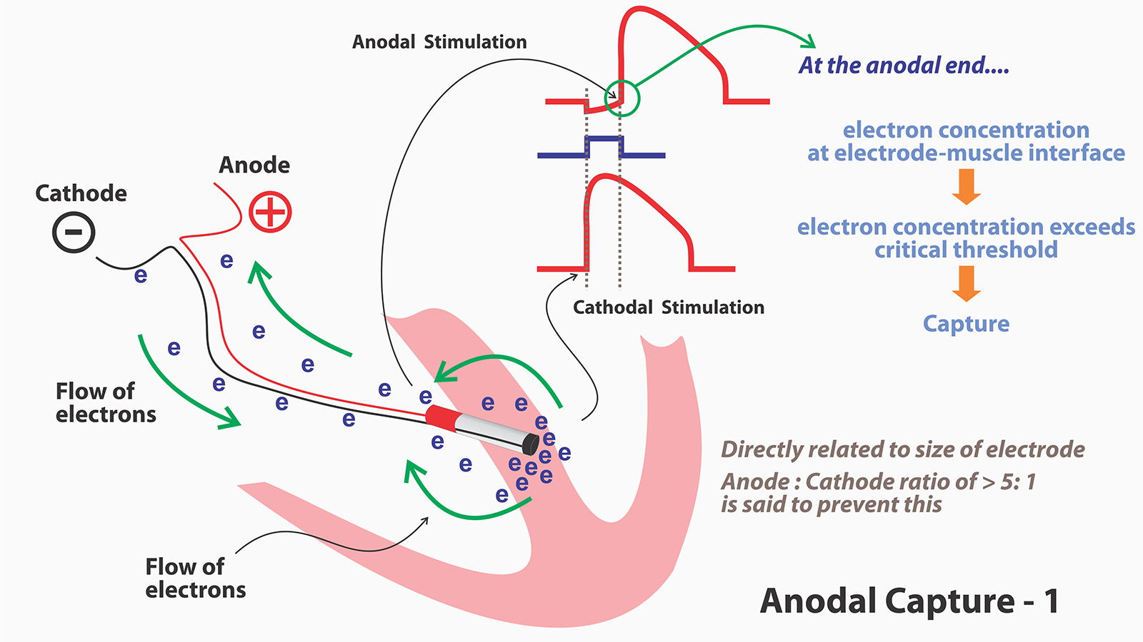
Figure : Principle of anodal capture.
It was also noted that, during anodal capture, the resulting myocardial refractory period was shorter than for comparable cathodal captures. (This happens because of initial hyper-polarization during electron concentration at the myocardial- anode interface). This raised the theoretical possibility of R-on T pacing as the myocardium recovers rapidly. Certain tests done during 70s and 80 demonstrated that this is indeed possible at fast heart rates in acutely diseased myocardium which led to VT/VF.
As anodal capture thresholds are anyway high, it was thought that by increasing the geometric size of the anode could prevent capture by avoiding electron concentration. However in practice this was not the case and anodal capture was seen even at standard pacing outputs (5V, 0.5 ms) despite having large anodes.

Figure : The basis of arrhythmogenicity in bipolar pacing. This was initially noted in patients with temporary bi-polar wire but later seen in permanent systems too. However that was nearly three decades ago and with modern leads and synchronous pacing, its is now only a theoretical possibility.
However those tests were done in asychronous pacing at fast heart rates which are not clinically seen these days. Currently most pacing is synchronous and all efforts are taken to minimize pacing. Furthermore, most of the ring electrode in modern systems (especially when implanted in the septum) lies in blood rather than in contact with the myocardium. All of this makes anodal stimulation only of theoretical interest in modern pacing systems – except for one reason – which is why it is discussed here in the first place : CRT
In CRT, the sometimes the LV lead is configured to pace from its tip (Cathode) to RV ring (anode) [LVtip – RVring]. The necessity for this situation arises when there are phrenic nerve capture issues. When the LV is paced from the tip of LV electrode, the RV ring is can cause anodal stimulation at high outputs. Actually three wave-fronts are described – the LV tip Cathodal capture wavefront, RV tip cathodal capture wavefront and RV ring anodal capture wavefront. It is thought that these triple wavefronts as cause for not responding to CRT. (More details in CRT Programming section later on)
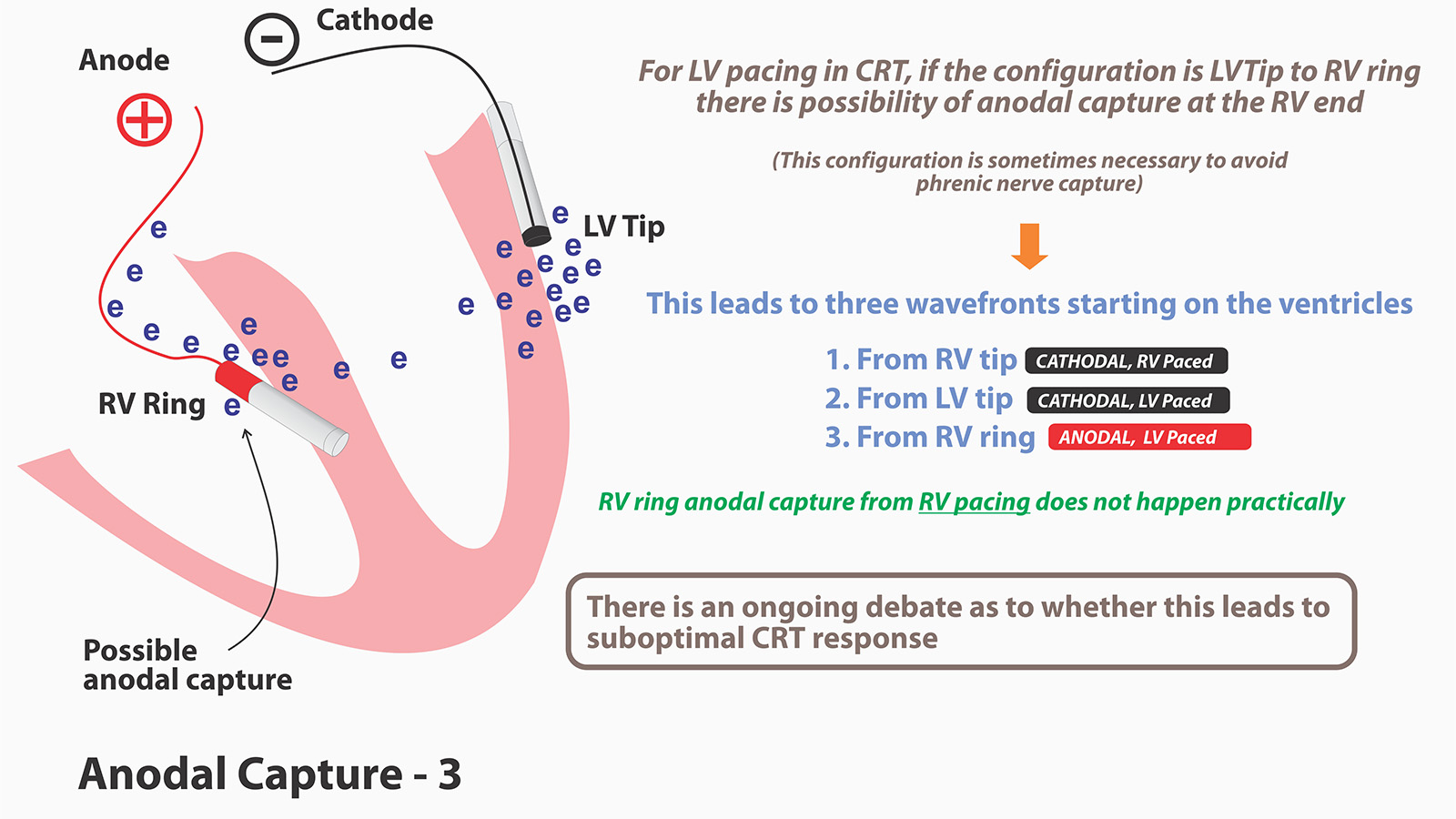
Figure : Anodal Capture in CRT. As depicted three wavefronts can occur in the ventricles. Their occurrence and manifestation depends on the RV-LV timing offsets. LV first pacing is a common setting and in this situation, anodal capture in the RV ring can actually mimic RV pacing as the wavefront will begin in the RV. Whether this leads to sub-optimal CRT response is being debated. However because of the benefits of modern quaripolar LV leads, the necessity to program RVRing-LV Tip configuration is becoming rare. Another possible method of reducing anodal capture in CRT-D is to use an integrated RV lead where the RV shocking coil is the ring electrode and by virtue of its large surface area, anodal capture is unlikely.
Lead construction
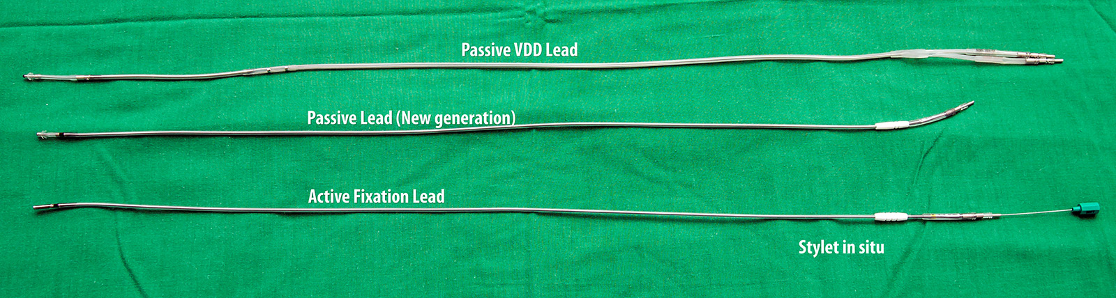

Figure : Comparison of three types of bipolar bradycardia pacing leads – The left side (top) lead is a older generation passive fixation lead. The ring-tip distance is large. Center lead and right side (bottom) lead are modern leads that represent a smaller distance between the ring and the tip.
Earlier leads did not have a lumen for a stylet nor an anchoring mechanism – hence lead dislodgements were common. Subsequently a lumen was built into the lead which enabled a stylet to guide the lead to the desired location (RV apex at that time) – however, it was only when tined (flanged) tips were built, that the lead dislodgements became less as the leads now had a fixation mechanism. These tines were passive fixators – i.e. they depended on anchoring themselves to the RV trabaculae (or RA appendage trabaculae). To overcome this and to facilitate fixation of the lead in any place, active fixation leads with extendable screws were developed and they represent the present day leads.
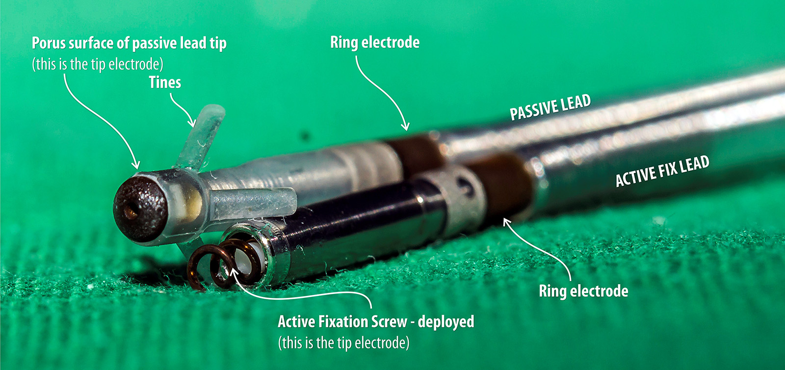
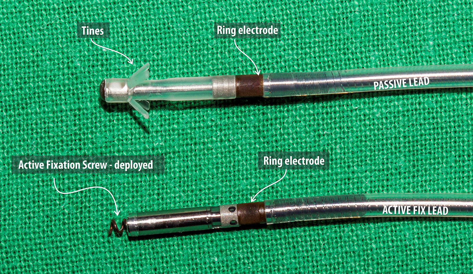
Figure : Comparison of active and passive fixation leads – Passive fixation leads have tines (fanges) at their ends, these tines get entangled in the RV trabaculae. Therefor these leads were basically designed for apical pacing. In contrast, active fixation leads have a screw in the tip which can be deployed from the other end thus enabling fixation to any place within the heart. In some brands and models, the screw itself is part of the tip electrode and the length of screw curve determines the overall surface geometry. The screw electrode surface is slightly rough to further suppress polarization – but the overall screw size (lead tip geometric size) is similar to a passive lead tip thus maintaining adequate current density
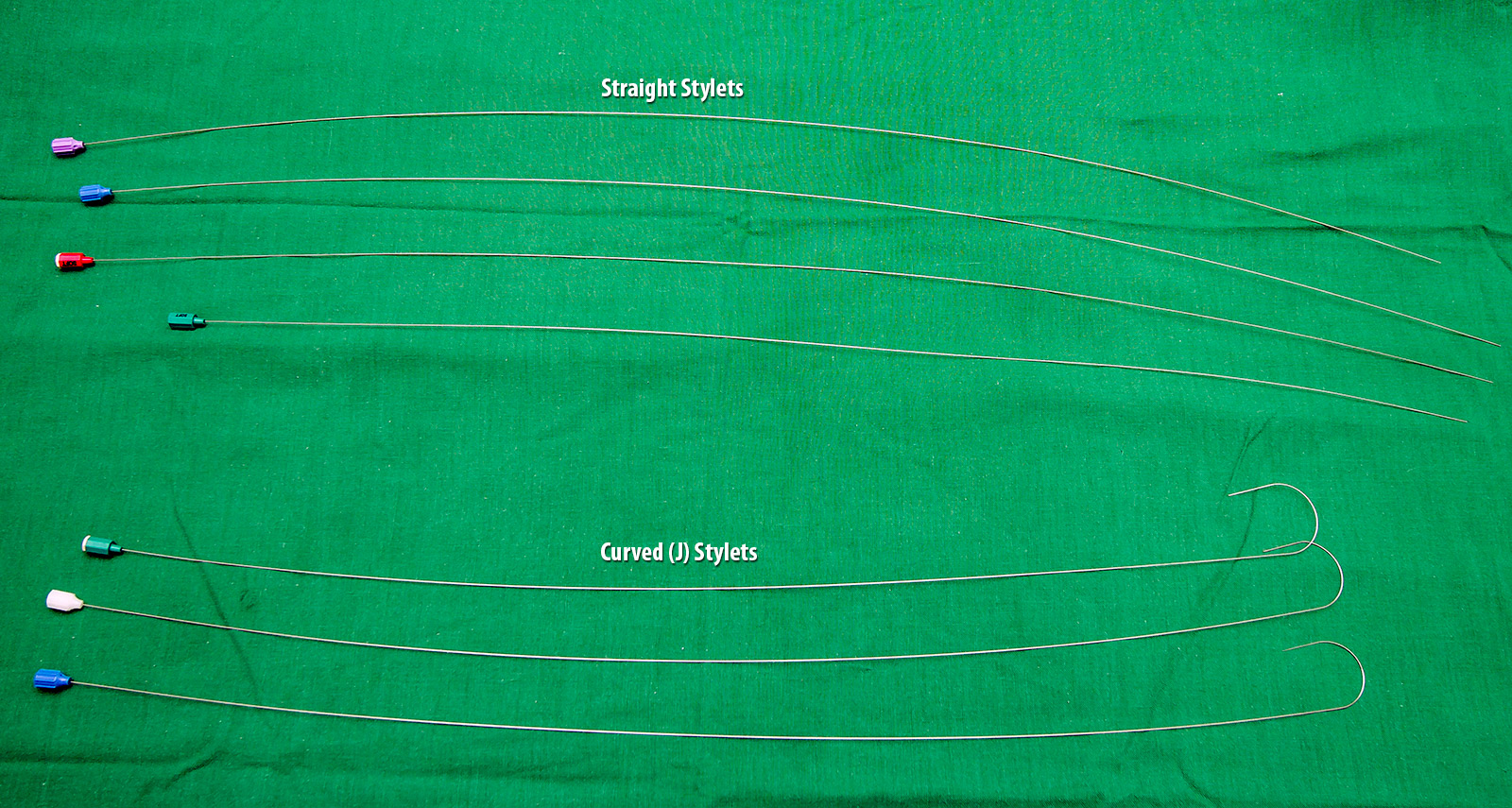
Figure :Stylets – Stylets enable precise placement of leads in any wall of the heart by giving the lead some tempoarary changeable stiffness. Theses stylets come in various stiffness and lengths which can be adapted to suit the anatomy and intended pacing location. Soft stylets give more leverage in manipulating a lead to the desired position (e.g. mid septal pacing) and stiff stylets help maintain stability until fixation (e.g. ICD leads, tricky positions)
Early on it was noted that after fixation, with time, the lead impedance went up leading to significant battery depletion. This phenomenon is due to inflammation and subsequent fibrosis with scar tissue formation at the tip – muscle interface. Impregnation of a steroid at the lead tip prevented this excessive scarring and helped to maintain chronic lead impedance acceptable, thus preserving battery life. Therefore all modern leads have steroid eluting tips.
Majority of bipolar bradycardia pacing leads are made of concentrically (co-axial) placed conducting metal coils embedded in insulating material. Conducting coils are made of metal alloys which gives good tensile strength while maintaining good electrical characteristics. The construction of a coil gives reversible flexibility in all axes while facilitating transmission of torque without twisting the lead body.
The insulation is made of a combination of polyurethane, silicone rubber and fluoropolymers (PTFE & ETFE) for optimal flexibility, resistance to abrasion and lubricity to be navigated inside vascular structures.
Co-axial nature of the conductor placement gives redundancy for critical pacing: If the external coil fractures or there is an external surface insulation breach, the internal coil (surrounded by its layer of insulation) can continue to pace in the form of a uni-polar lead. All modern pacemakers can electronically detect external conductor errors and switch to uni-polar pacing to maintain rhythm until the lead is replaced.

Figure : Lead construction – The leads are made of two concentric coils of conductors embedded in layers of insulation. The concentric nature of the coils give redundancy in pacing as the inner conductor can work as in a uni-polar system if there is a fracture or breech of the external conductor.
The lead connects to the device using the lead connector and this connector and connection port design is an international standard (named IS1 pacing connector) which all manufacturers adhere to. This is to provide inter-manufacturer compatibility for lead connections.

Figure : IS 1 connector – This is an international standard for connecting bradycardia pacemaker leads to devices.